Vhdl Program For Parity Generator
I have a little problem coding a 4-bit odd parity generator with only NAND as logical operator in VHDL. I have the entity done, like you see in code but struggle doing the architecture with only NAND as logical operator.
Code Download Features • VHDL source code of a Parity Generator component • Configurable number of input bits • Configurable selection for even or odd parity Introduction Parity evaluates whether the number of “1” bits in a binary code is odd or even. This provides a simple means of error checking. There are two types of parity with opposite results. Even parity results in a “1” if there are an odd number of “1” bits in the original code, and “0” if there are an even number. The even parity bit can be appended to the code to make the number of “1” bits even.
Odd parity results in a “0” if there are an odd number of “1” bits, and “1” if there are an even number. The odd parity bit can be appended to the code to make the number of “1” bits odd. This page details a Parity Generator circuit, written in VHDL, for use in FPGAs and CPLDs. The component reads in a binary code over a parallel interface and outputs the parity bit.
Mulab 7. The size of the input code is configurable, as is whether the output parity bit is even parity or odd parity. It was designed using Quartus Prime, version 17.0.0.
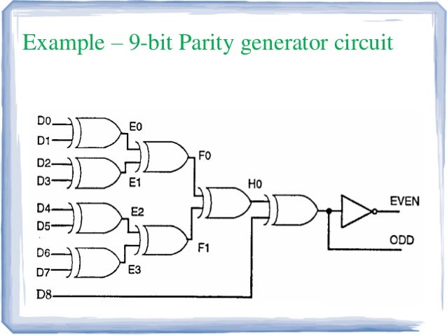
Theory of Operation This Parity Generator uses simple XOR logic. As the truth table in Figure 1 shows, an XOR gate outputs a ‘0’ if the number of high inputs is even and a ‘1’ if the number of high inputs is odd. XOR Truth Table. Input A Input B Output 0 0 0 0 1 1 1 0 1 1 1 0 Figure 1 illustrates the Parity Generator. The parity_eo input makes the correction for even or odd parity, and the cascading XOR gates keep a running evaluation.

Each new gate in the series decides if the next bit in the sequence makes the running total odd or even. Once all the input bits are evaluated, the output parity presents the final result. Parity Generator Circuit Configuring the Parity Generator The Parity Generator is configured by setting the GENERIC parameters in the ENTITY. Table 2 describes the parameters. Generic Parameter Descriptions.
When valid_in is ‘1’ it will accept serial input and that serial input goes for parallel output. After receiving eight bit of serial input this block converts the serial input to parallel output. Valid_out signal goes ‘1’ after receiving eight bytes of serial data & gives parallel data on the data_o. After valid_out goes high parity_out signal gives parity of the input data.
Valid_out signal goes high on each eighth clock cycle & remain high for one cycle.