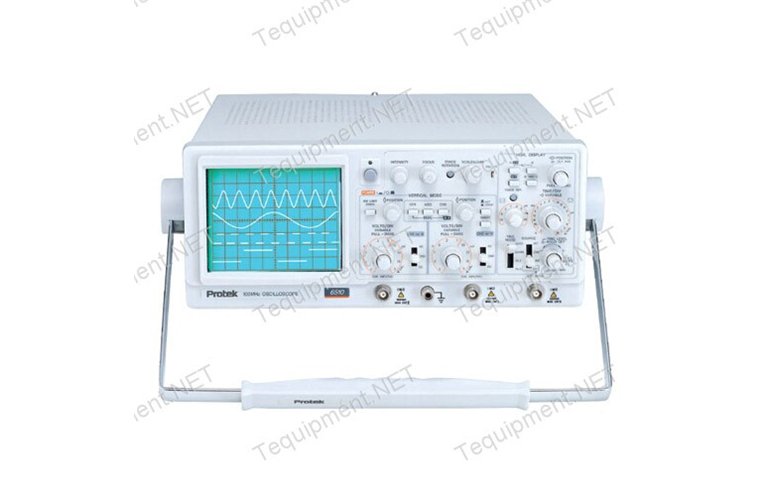
Protek 6510 Oscilloscope Service Manual
Oct 2, 2012 - Download service manual 2006 honda elite - 0 views. Service manual. Download hung chang oscilloscope manual - 0 views.
Funny thing -- it turns out that the Protek site has a P3502C service manual! It's the same scope as the P3502 except for one added feature for component testing. I bet this manual is just what you're looking for. Can't get a clear picture?
You mean you can't focus the beam with the focus knob? If I had to guess. There are some service adjustments for focus covered in the manual I think. Also could be a problem with the focus circuitry. Could be a tube problem. Not sure what you mean by being unable to 'get things to move around ground?'
Let me know if I can help. Cab drivers cough linctus. I am starting to get a better handle on how these things work so maybe I can steer you in the right direction.
Meanwhile here is a great troubleshooting guide that applies to all scopes even tho it is written by/for Tek. I couldn't make out the settings but that is ok. Interesting behavior!!
Take a look at that PDF and just kind of skim through it and get the gist. Their approach is--diagnose from the front panel. That's what we'll try and do. So, step one, diagnose the faulty section.
The o-scope is made up of several main sections. The power supply of course provides various voltage to all the other sections. The vertical section controls the position of the beam on the vertical axis. At present I'd put my money on a problem with the vertical section. The horizontal section is what sweeps the beam from left to right. It also is responsible for triggering when to sweep, blanking the beam when sweeping right to left to start another sweep.
You seem to be having a problem getting the beam to show up below a certain point on the screen. The vertical position adjust is part of the vertical section circuitry. So maybe that has something to do with it. In the PDF take a look at the chapter called 'Troubleshooting the Vertical Section' Let's see if we can isolate down to the block, circuit and then component levels.
I am kind of winging it here. First off, does this behavior only happen on channel A? Or does this also happen on channel B? Second, when you set Channel A coupling to AC and adjust the position knob, what happens? What about when you set coupling to DC? Third, when you set Channel B coupling to AC and adjust the position knob, what happens? What about when you set coupling to DC?
There's two obvious things common to both CHA and CHB, all coupling -- the CRT itself and the vertical amplifier (the 'Output' triangle below). This seems like an electronics problem, not a CRT problem. The other thing common to both channels is the block labeled 'Mode Control Logic / Vertical Select / Trigger Select' -- I'm not 100% sure what these do, but the problem could lie there as well. I'll go look at circuit diagrams and see if I can get a sense of what these do. Do you have an oscilloscope probe? If so, could you (1) plug the probe into the ChA input and then (2) hook the probe to the calibration pin on the front panel and (3) film the waveform and show what happens when you move the position knob and then post it to youtube for me to look at?
I'm curious to see what it looks like when displaying a waveform. Thanks, Michael. PPS: when you display the waveform, see what it looks like and how it behaves with Volts/Division at different settings from low to high. What I predict is going to happen is that the part of the waveform appearing above the top half of the screen will look normal while the bottom half will look wonky. If you adjust the position and volts/div so that the trace fits in the top half of the screen, it'll look ok. But if you then change volts/div so that the trace takes up more vertical space, or if you reposition the trace lower, the bottom half will be wonky.
Let's see if I am right. Yup, just put the time/div indicator on X-Y Normally the horizontal sweep is controlled by a periodic, regular timing signal. In X-Y mode, CHB becomes the source for the sweep. That is to say, CHA deflects the trace in the Y axis, and CHB deflects the trace in the X axis (or maybe it is the other way around, but you get the idea). The result is you plot Lissajous patterns on the scope which is useful for diagnosing components, for example.
You'd feed a frequency into a component and measure the signal on the input (CHA) and output (CHB) sides to measure phase shift. The actually goes into this in detail since the C model includes the frequency generator to input the signal. Otherwise, on the non-C model, you have to have a separate frequency generator. So the lissajous pattern shows phase shift between two signals.